Showing posts with label controller. Show all posts

Sunday, July 18, 2010

Integrator Circuit

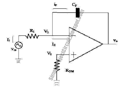
Integrator op-amp this circuit also comes from inverting circuit with the feedback prisoner is changed with capacitor. This is the figure of the Integrator Circuit.


Usually circuit for application there are addition of parallel prisoner with capacitor with name of RF. Integrator circuit which has not in adding parallel prisoner with capacitor. ROM Value is between zero up to R1.

Touch Switch Circuit Using Logic Control

This is a touch circuit that is used as a latching circuit to switch a LED ON and OFF by physically touching the ON metal plate or OFF metal plate. This circuit is based on logic gate for control the operation. This is the figure of the circuit.


It is important to ensure that 9V battery is used as its DC source. If one uses the mains supply to step down the voltage using a transformer for rectification and filtering to get the 9V DC supply, ensure that the transformer is designed in such a way that it follows the safety standard requirement of UL. This is important to ensure the safety of the user that is using the metal contacts to ON/OFF the LED. [Schematic diagram source: Electronics Project Design].

Simple Level Control and Attenuator

This is a design circuit for the level control, buffer and attenuator. This circuit is control using transistor. The buffer stage is used to ensure that the impedance seen by the attenuator is low, regardless of the pot setting. This is the figure of the circuit.


This is a simple form circuit. This arrangement is not as elegant as some others I have seen, but is quite acceptable and introduces little distortion. The loss introduced by this stage is about 0.05dB, which can be considered negligible. The BC559 transistor will need a small heat sink, as it is operating at a current of about 12mA, so dissipation is 140mW. The level control is a single gang linear pot, and as shown, the attenuator provides a passably constant output impedance of 560 Ohms at all output settings. If desired, the output can be calibrated in Volts, with the ranges 3V, 300mV, 30mV and 3mV. Attenuator accuracy is very good, provided 1% resistors are used for all ranges.

Simple DC Motor Control Circuit

This is circuit for control the DC motor. This circuit is control and work with based on transistor. This is a simple circuit. Here’s the figure of the circuit.


The S1 and S2 are normally open, push to close, press button switches. The diodes can be red or green and are there only to indicate direction. You may need to alter the TIP31 transistors depending on the motor being used. Remember, running under load draws more current. This circuit was built to operate a small motor used for opening and closing a pair of curtains. As an advantage over automatic closing and opening systems, you have control of how much, or how little light to let into a room. The four diodes surrounding the motor, are back EMF diodes. They are chosen to suit the motor. For a 12V motor drawing 1amp under load, I use 1N4001 diodes.

Simple 4-Transistor H-Bridge

This is a simple design circuit for transistor bridge. This circuit is used 4 transistor for built the circuit. This is the figure of the circuit.


2N2905 and 2N2219 transistors are no longer being produced; I use 2N2907 and 2N2222 transistors in this circuit, with good results. You absolutely must use one bias resistor per transistor; I attempted to simplify the circuit by connecting the respective transistors' bases (so each pair of transistors could "share" a resistor) -- this made for a circuit that was simpler, much easier to freeform, and completely non-functional. This efficiency of this design is driven by 2 things -- the efficiency of the motor it's driving, and the size of the bias resistors. Just to make life interesting, these things are interrelated (more on this later).

Simple Analog Multiplier Circuit

This is a circuit for a simple embodiment of the analog multiplier. This circuit provides three quadrant analog multiplication which is relatively temperature insensitive and which is not subject to the bias current errors which is plague most multipliers and circumvents many of the problems associated with the log-antilog circuit. This is the figure of the circuit;


By considering A2 as a controlled gain amplifier, amplifying V2, whose gain is dependent on the ratio of the resistance of PC2 to R5 and by considering A1 as a control amplifier which establishes the resistance of PC2 as function of V1, circuit operation may be used. It is seen that Vout is a function of both V1 and V2 in that way. Drive for the lamp L1 is provided by the control amplifier(A1). L1 is driven by A1 until the current to the summing junction from the negative supply through PC1 is equal to the current to the summing junction from V1 through R1 when an input voltage (V1) is present. This forces the resistance of PC1 to a value proportional to R1 and the ratio of V1 to V- since the negative supply voltage is fixed. L1 also illuminates PC2 and causes PC2 to have a resistance equal to PC1 if the photoconductors are matched. The controlled amplifier (A2) behaves as an inverting amplifier whose gain is equal to the ratio of the resistance of PC2 to R5. Vout becomes simply the product of V1 and V2 if R5 is chosen equal to the product of R1 and V-. To provide any required output scale factor, R5 may be scaled in powers of ten.

Since the T.C. of resistance is related to resistance match for cells of the same geometry, PC1 and PC2 should be matched for best tracking over temperature. Varying the value of R5 as a scale factor adjustment is used to compensate small mismatches. The photoconductive cells should receive equal illumination from L1, a convenient method is to mount the lamp midway between them. Controlled spacing and a thermal bridge between the two cells to reduce differences in cell temperature is provided by this mounting method. To the use of FET’s or other devices to meet special resistance or environment requirements, we can extend this technique.

An inverting output whose magnitude is equal to one-tenth the product of the two analog inputs is given on this circuit. Positive value is restricted for input V1 but V2 may assume both positive and negative value. By the lamp time constant, his circuit is restricted to low frequency operation. To minimize errors due to input offset current as outlined in the section describing the photocell amplifier, R2 and R4 are chosen. To reduce in-rush current when firdt turning on the lamp (L1), R3 is included.

[Circuit source: National Semiconductor Notes]
Simple Loud Hailer Circuit

This is a simple and useful circuit project of loud hailer the circuit uses only one transistor connected with transformer which puts out a loud sound. The circuit can be easily fixed in a metal package with the speaker mounted on the top. Heat sink is essential for the transistor or it will burn out, fix the circuit in metal package and also use this metal package as heat sink of transistor. This is the figure of the circuit;


Use carbon mic or telephone mic/telephone transmitter element. The circuit can be build inside of a speaker trumpet like the loudhailers available in market. Make sure that the mic is isolated from the speaker to prevent feedback. Use the transformer which will able to provide 5 watt output power.